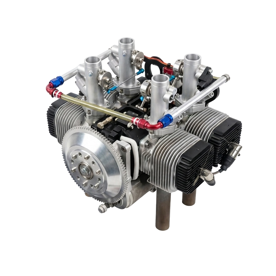
550 Electronic Fuel Injection Aviation Piston Engine
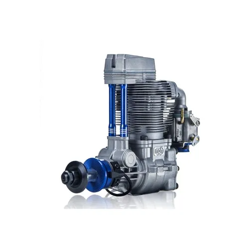
The 550 Electronic Fuel Injection Aviation Piston Engine (hereinafter referred to as the “550 Engine”) is a unit that provides propulsion and electrical power to unmanned aerial vehicles (UAVs).[cite: 1].
USD · Volume pricing available
Kategorie:
Certifications
Global Shipping 7-14 Days
DHL, FedEx, UPS, Air & Sea
Genuine Products
Authorized distribution
Export License Ready
ECCN, CO, CI, PL, EUS docs
24/7 Tech Support
Pre & post sales
Export Compliance
9A012AI confidence 75% · License required for certain destinations. License exceptions GBS/CIV may apply for allied nations.
Buyer Tier Benefits
Tier discounts stack with volume pricing. Automatically applied after your first order.
1. Purpose and functions of the product
The 550 Electronic Fuel Injection Aviation Piston Engine (hereinafter referred to as the “550 Engine”) is a unit that provides propulsion and electrical power to unmanned aerial vehicles (UAVs).. This type of engine features a simple and reliable design, high power-to-weight ratio, compact layout and stable performance..
As the propulsion system for the aircraft platform, the 550 propulsion system provides the UAV with the necessary thrust and also supplies power to the avionics..
2. Characteristics and main technical indicators
2.1 Functional requirements
- Launch method: The engine is equipped with its own electric starter, providing electric starting.
- Cooling method: The engine has an air cooling system.
- Lubrication method: Lubrication is carried out by oil mist (mixed system).
- Fuel type: Gasoline with an octane rating of 95 and higher.
- Communication functions: Capable of receiving control commands from the control computer (or integrated on-board computer) and adjusting engine speed accordingly; capable of transmitting to the control computer parameters of throttle position, speed, intake temperature, cylinder temperature, exhaust gas temperature, etc..
2.2 Operational requirements
2.2.1 General characteristics
- Maximum speed: ≥ 6300 rpm.
- Maximum power at zero altitude: ≥ 37 kW.
- Minimum specific fuel consumption:
- 1) Cruise: < 380–460 g/(kWh).
- 2) Maximum power mode: < 550 g/(kWh).
- Minimum stable speed: < 2000 rpm.
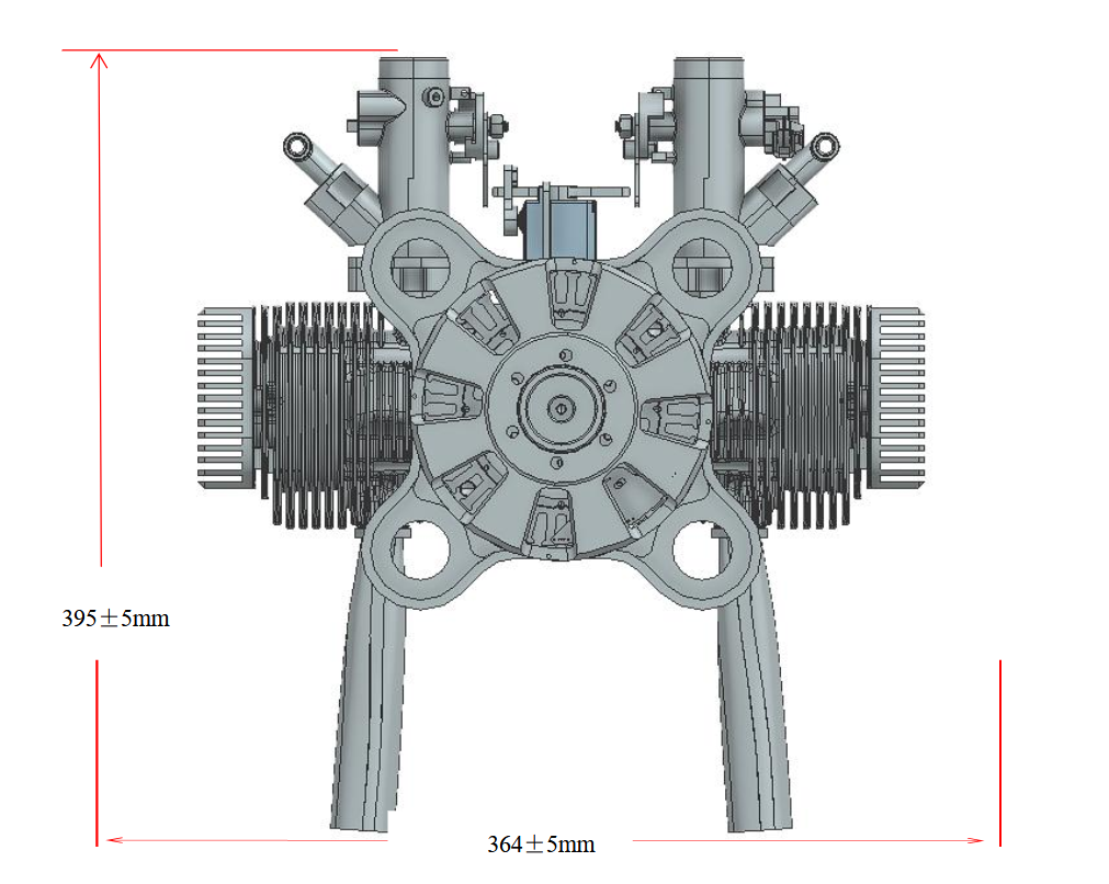
- Dimensions (L×W×H): (364±5) mm × (372±5) mm × (395±5) mm.
- Weight: ≤ 22.5 kg (including engine block, intake and exhaust system, injection control unit).
- Appearance requirements:
- The surface must be flat, smooth, without damage, rust, mold, stains, coating peeling, obvious scratches and burrs.
- Structural parts and control elements must not have mechanical damage; connections and fasteners - without corrosion, damage, loosening and deformation; welds are smooth, without slag and cracks; plastic parts - no swelling, cracks or deformations.
- Cables and harnesses must be laid rationally, with fixation and protection measures.
- Text, symbols, markings and indicators must be legible.
- Markings and designations: The product is equipped with a nameplate indicating the name, code, serial number, production date and other information.
2.2.2 Launch characteristics
- Number of startup attempts: The engine should start successfully within 3 attempts.
- Starting at low temperatures: Can be started in low temperature conditions down to -40°C (use of auxiliary heating equipment supplied in the kit is allowed).
2.2.3 Electricity generation characteristics
- Generation power: ≥ 2 kW.
2.3 Engineering requirements
- Reliability: Mean time between failures MTBF(01) ≥ 300 h.
- Maintainability: Average recovery time MTTR ≤ 1.4 h (at baseline).
- Security:
- 1) Providing a technical description, operation and maintenance manual, product form (passport) and documents confirming quality.
- 2) Providing the necessary auxiliary equipment, tools, spare parts (including wearing parts, consumables and parts with limited service life) to ensure operation and repair.
- Security:
- 1) Cables and connectors are protected against incorrect connection (“fool proof”).
- 2) Metal structural elements do not have sharp corners or edges.
- 3) There are no oil leaks during engine operation.
- 4) The engine has an overspeed protection function.
- 5) The outlet of high-temperature exhaust gases is directed away from the UAV fuselage.
- Testability: The injection control unit is capable of monitoring throttle position, engine speed, cylinder temperature, exhaust temperature, intake temperature, fuel pressure, etc..
2.3.1 Environmental conditions (Adaptability)
- Operating temperature: -50°C ~ +55°C (start at -40°C, auxiliary heating possible).
- Storage temperature: -50°C ~ +65°C.
- Relative Humidity: (95±5)% (at 30°C ~ 60°C).
- Vibration: ≥ 2g (15Hz ~ 500Hz ~ 15Hz).
- Shock loads: vertically ≥ 20g, along the transverse and longitudinal axes ≥ 15g.
- Low pressure: Capable of withstanding low pressure conditions equivalent to 7000m altitude.
- Salt fog: Resistant to salt spray.
- Mold: Resistant to mold and mildew.
- Rain: Provides protection from moderate rain.
- Application altitude: Able to start and operate normally in high altitude conditions at altitudes of up to 5000 meters.
2.3.2 Electromagnetic compatibility (EMC)
- Internal Compatibility: The product is compatible when used independently.
- Mutual compatibility: After installation on a UAV, the product is capable of working in conjunction with other equipment of the device.
2.3.3 Interchangeability
- Field replaceable units (LRUs) of the same model and functionality are interchangeable.
| № | Name | Quantity | Note |
|---|---|---|---|
| 1) | Electronic injection control unit (EVT/ECU) | 1 piece | |
| 2) | Spark plug | 4 pcs. | |
| 3) | Ignition module (CDI) | 2 pcs. | |
| 4) | Fuel injector | 4 pcs. | |
| 5) | Air filter | 4 pcs. | |
| 6) | Exhaust pipe | 4 pcs. |
2.3.4 Transport requirements
- Return transportation: The product is equipped with a special shipping container that meets the requirements of road and rail transportation.
- Transportation within the device: After installation on the UAV, it satisfies the requirements for transporting the device.
2.3.5 Resource (Service life)
- Time to first overhaul (TBO): ≥ 250 h.
- Shared resource: ≥ 500 h.
2.3.6 Software development requirements
- A modular software architecture with expandability is used; proven software is used and inherited.
- Software development complies with GJB 2786A-2009 General Requirements for Military Software Development, and documentation complies with GJB438B-2009 General Requirements for Military Software Documentation..
3. Composition, structure and principle of operation
3.1 Product composition
The 550 engine is a four-cylinder, horizontally opposed, two-stroke, air-cooled piston engine. Uses an electronic fuel injection system. It consists of an engine cylinder block, an electronic injection control unit and other elements.
3.2 Product structure
The main components of the structure include: Engine body/block, Ignition system (including CDI and spark plugs), Fuel injection system (EV, injectors), Intake and exhaust system (Throttle body, air filter, exhaust pipe), and Integrated starting and generation system (Alternator/starter).
3.3 Operating principle
- The 550 engine uses an electronic fuel injection system (EFI system). The engine uses pressure from the combustion of gasoline to drive the pistons, converting their linear reciprocating motion into rotational motion through a crank mechanism to rotate the propeller and create thrust..
- The EVT system relies on various sensors to determine engine operating conditions (such as speed, intake temperature, barometric pressure, throttle angle). After calculations in the control unit (ECU) and adjustments according to the curves stored in the read-only memory (ROM), the system precisely controls the injection time and volume of the electromagnetic injectors. This ensures an optimal air-fuel mixture ratio in all operating modes, achieving the best power and efficiency indicators.
- The electric starting system uses an integrated motor-generator (starter-generator) to rotate the engine crankshaft. The motor-generator is installed directly on the engine, which greatly simplifies the starting process and makes it safe and reliable.
4. Technical features of the product
The main technical features of the 550 engine include:
- Simple and reliable design, low weight, space-saving layout.
- High operating efficiency (efficiency), high power-to-weight ratio.
- Integrated starter-generator design with main engine block - highly integrated, easy to operate and maintain.
5. Interfaces
5.1 Mechanical interfaces
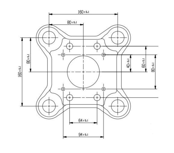
- 5.1.1 Installation interface on the UAV body: The installation dimensions of the motor bracket for mounting on the UAV body have a tolerance of ±0.5 mm.
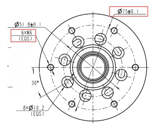
- 5.1.2 Propeller installation interface: According to the assembly drawing.
- 5.1.3 Fuel system interfaces:
- a) 1 fuel supply channel (input);
- b) 1 fuel return channel (return).
5.2 Electrical interfaces

- a) 1 DC input interface;
- b) 1 CAN bus interface;
- c) 1 full duplex RS232 communication interface.
6. Maintenance instructions
Based on the results of life tests of the 550 engine, a schedule and list of maintenance work (MOT) during the service life were developed.
6.1 Field maintenance (on site)
Performed by the user, has a low level of complexity. Main service intervals: 50h, 100h, 250h, 350h, 400h and 500h. After 500 hours of operation, the engine reaches the limit of its service life; The manufacturer's technical specialists will give a professional recommendation on the need to replace the engine. The permissible deviation of maintenance time should not exceed 10 hours.
| System | Part name | Qty | 50h | 100h | 250h | 350h | 400h | 500h |
|---|---|---|---|---|---|---|---|---|
| Ignition system | Spark plug | 4 | R | R | R | R | R | R |
| High voltage cap | 4 | C | C | C | C | C | C | |
| CDI (functions, appearance) | 2 | C | C | C | C | C | C | |
| Cylinder block | Connecting rod lower end bearing | 2 | C | C | C | C | C | C |
| Cylinder head bolts | 16 | T | T | T | T | T | T | |
| Cylinder temperature sensor | 4 | C | C | C | C | C | C | |
| Generator | 1 | C | C | C | C | C | C | |
| Throttle body | 4 | C | C | C | C | C | C | |
| Exhaust system | Exhaust pipe | 4 | C | C | C | C | C | C |
| Exhaust window gasket | 4 | R | R | R | R | R | R | |
| Fuel system | Bypass (hollow) bolt | 4 | C | C | C | C | C | C |
| Bypass bolt gasket | 4 | C | C | C | C | C | C |
Note: C - Check (Check, clean, replace if damaged), T - Torque (Check tightening torque), R - Replace.
6.2 Factory maintenance
Performed by the manufacturer, has high complexity. Main service intervals: 150h, 300h, 450h, 550h. The permissible deviation of maintenance time should not exceed 10 hours.
| System | Part name | Qty | 150h | 300h | 450h | 550h |
|---|---|---|---|---|---|---|
| Ignition system | Spark plug | 4 | R | R | R | R |
| High voltage cap | 4 | I | I | I | I | |
| CDI (functions, appearance) | 2 | I | I | I | R | |
| Cylinder block | Crank mechanism | 1 | C | C | C | C |
| Main bearing | 3 | C | C | C | R | |
| Front and rear crankshaft oil seals | 2 | C | R | C | R | |
| Connecting rod lower end bearing | 2 | I | I | I | I | |
| Cylinder block (jacket) | 4 | C | C | C | R | |
| Piston | 4 | C | R | C | R | |
| Piston ring | 4 | R | R | R | R | |
| Piston pin retaining ring | 8 | R | R | R | R | |
| Cylinder head gasket | 4 | R | R | R | R | |
| Cylinder block gasket | 4 | R | R | R | R | |
| Cylinder head thread | 8 | C | C | C | C | |
| Engine block bolts | everything | C | R | C | R | |
| Cylinder temperature sensor | 4 | I | I | I | R | |
| Generator rotor | 1 | C | C | C | R | |
| Generator stator | 1 | C | C | C | C | |
| Shock absorbing cushion | 4 | R | R | |||
| Intake system | Throttle body | 4 | C | C | C | R |
| Exhaust system | Exhaust pipe | 4 | C | C | C | C |
| Exhaust window gasket | 4 | R | R | R | R | |
| Mounting elements | Bracket cushion | 4 | C | R | C | R |
| Fuel system | Bypass (hollow) bolt gasket | 4 | R | R | R | R |
| Bypass (hollow) bolt | 4 | R | R | R | R | |
| Fuel filter | 1 | C | R | C | R |
Note: I - Inspect, C - Clean, R - Replace.
6.3 System warranty period
- The warranty period for the system is 3 years. Breakdowns caused by the product itself are repaired by the manufacturer free of charge; Malfunctions caused by improper operation and damage during testing are serviced by the manufacturer for a fee.
- Wearing parts and parts with a limited service life are not eligible for free service. The user must check them regularly and, if replacement is necessary, contact the manufacturer.